

How to make a DIY scissor lift

Recently, after pondering a way to level out long workpieces when working with my small bench drill, I came up with a rough design for what would ultimately become this nifty little gem.
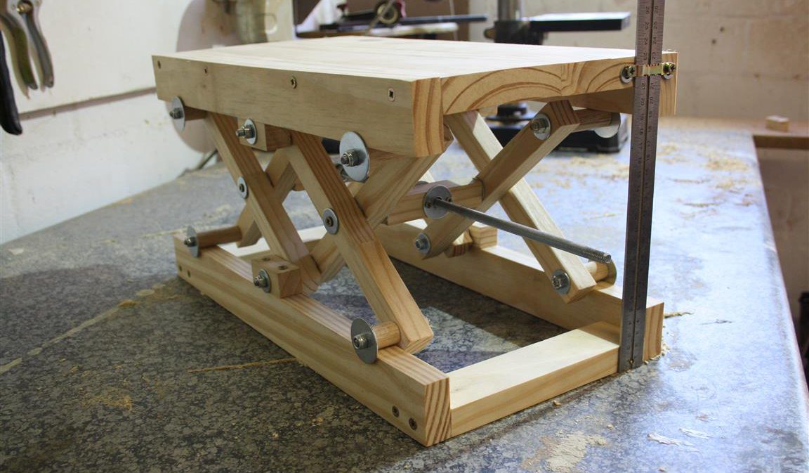
I operate the lift using my 12V Bosch ps130-2A cordless drill.
At it’s lower point it offers a 132mm high working platform while the small scissor lift platform can reach 300mm at its highest point.
Although this small gadget was made specifically for my drill press, the design can be scaled and adapted to be used for a number of different applications.
In this post, I will be sharing my drawings and build process for my version of a small DIY scissor lift.
Lumber cutting list – (PAR’ed Pine):
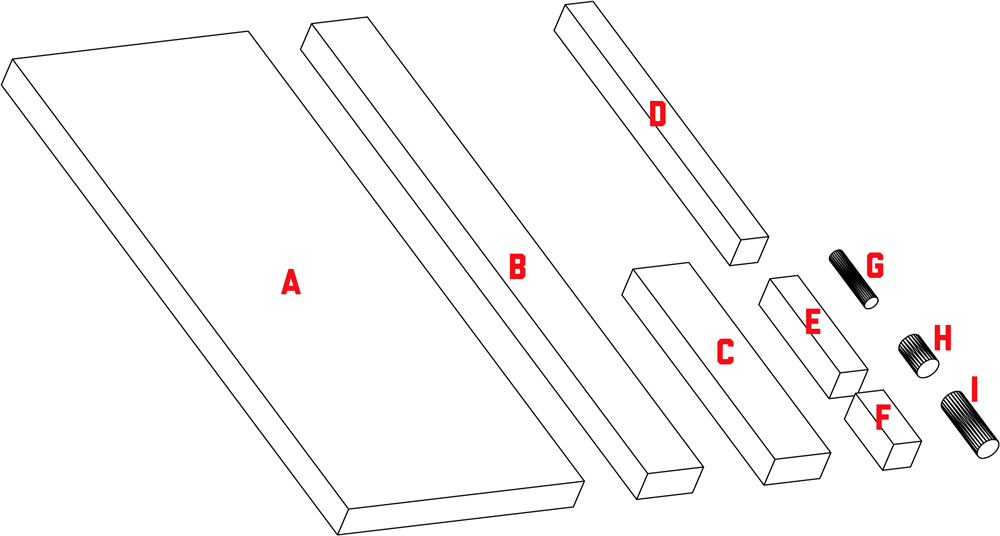
A x (1) – 440x186x22
B x (4) – 440x44x22
C x (2) – 168x44x22
D x (8) – 230x22x22
E x (2) – 92x22x22
F x (4) – 50x22x22
G x (8) – 46×10 Dowel
H x (4) – 24×16 Dowel
I x (4) – 47X16 Dowel
Other parts:
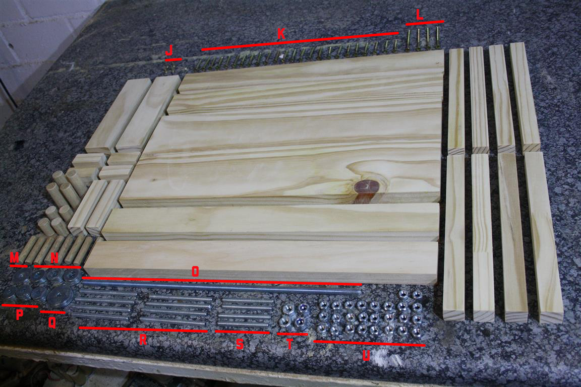
J x (4) – 6×10 screws
K x (24) – 8×35 screws
L x (4) – 8×70 screws
M x (2) – 10×30 Penny washer
N x () – 10×12 Washer
O x (1) – 10x Threaded rod
P x (20) – 6×20 Washer
Q x (4) – 6×40 Penny washer
R x (8) – 6×90 Threaded rod
S x (4) – 6×70 Threaded rod
T x (4) – 10mm Nuts (Two lock nuts)
U x (26) – 6mm Nuts (lock nuts)
Assembled dimensions

Get building – Step 1 – The top and base
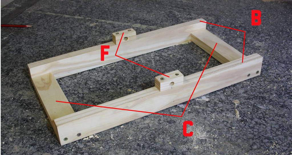
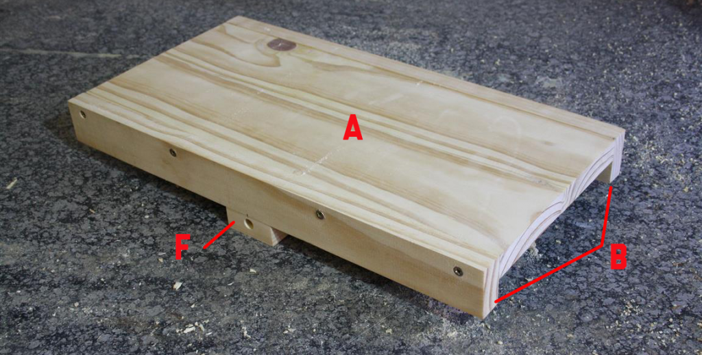

The top is assembled by fitting 2 of the “B” components to the sides of the “A” component, as shown in the photograph above. Thereafter prepare and fit an “F” component to the center of each one of the “B” components.
Preparation of the “F” component is done by drilling a 10mm hole as indicated by the diagram.
The base is assembled in much the same manner however the “A” component is replaced with 2 “C” components.

The assembly of the top and base is fairly straightforward with the only aspect that needs to be noted is the orientation of the 10mm hole in component “F“.
This will be the point where the scissor mechanism will fix to the top and base.
It is for that reason that the center point of this hole should be inline with the center point of the sliders when the lift is assembled.
The sliders are made using 16mm dowels. Therefore the center of the 10mm hole that needs to be drilled in component “F” should be 8mm from the edge that will be fixed to the “B” components.
Step 2 – The scissor mechanism
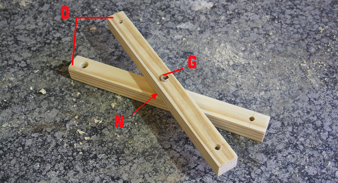

Of the 8 “D” components, 4 will be drilled in a 6-10-10mm pattern while the remaining 4 are drilled in a 6-10-6mm pattern (6 and 10 referring to hole size) as shown in the above diagram.
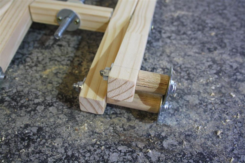
One of each of these will be assembled along with 1 “G” component (10x46mm dowel) and 1 10mm washer (“N“) to make up 1 of 4 scissor legs.
Push the dowel through the middle hole on one of the pegs, then add the washer followed by the other peg.
The purpose of the washer is to prevent the wood from grinding up against each other when the lift is being raised and lowered.
A 6mm hole needs to be added to the center of the 10mm dowel. This can be done before or after assembling the scissor leg.
Repeat this step 4 times to make all of the scissor legs.
Step 3 – Height adjustment mechanism
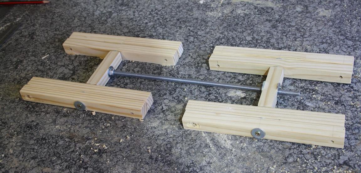

In this step, you will drill 10mm holes in the center of the 2 “E” components to accommodate the 10mm threaded rod.
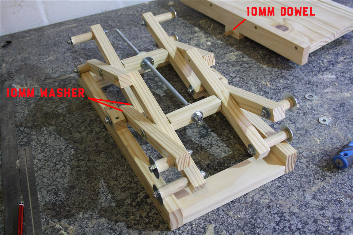
Fasten the threaded rod to one of these using 2 of the 10mm washers and the 2 10mm lock nuts, as shown to the left of the above image.
This will be the fixed point of the rod so the lock nuts should be fastened to a point where the rod can still turn within the “E” component.
As for the other “E” component, use a chisel and a mallet to enlarge the hole in the shape of a 10mm nut. (Refer to video for visual instruction)
After doing so the remaining two 10mm nuts (not lock nuts) can be inserted into the cutouts.
To prevent the nuts from slipping out of the wood when the jack is operated, they are secured with the 10mm penny washers (“M“).
By drilling 2 holes in the washers they can be attached to the wood using screws (“J“).
This will be the adjustable point.
When the adjustment mechanism has been completed, the 4 scissor legs can be attached.
This is done by simply using the 70mm screws along with 4 6mm washers to fix the legs to the assembled adjustment mechanism. Remember to add another 10mm washer between the scissor leg and the “E” component to prevent grinding of the wood when operating.
When attaching the scissor legs to the adjustment mechanism, the pegs with the 6-10-6 hole configuration should be toward the inside.
Note that the dowel is longer than the scissor leg assembly is wide. This means that when the screws are added and the legs are attached to the “E” components, the scissor mechanism should be able to move freely.
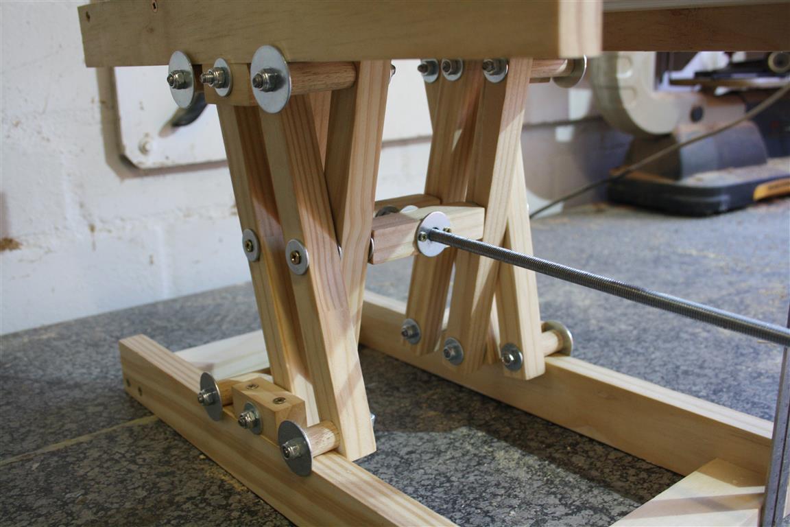
Step 4 – Attaching the sliders (16mm dowels)
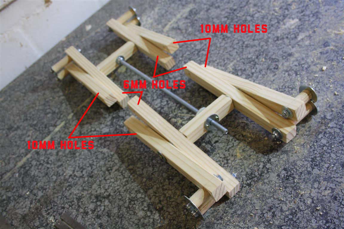
 Attaching the sliders is simple enough. Using the 4 short 6mm rods (“S“) for the short sliders (“H“) along with a 6mm washer toward the inside and a 6mm penny washer on the outside, attached the sliders with two 6mm nuts on either side of the rod (“U“). The process of attaching the long sliders is the same, however, instead of short rods and sliders, you will use the longer ones (“I” and”R“).
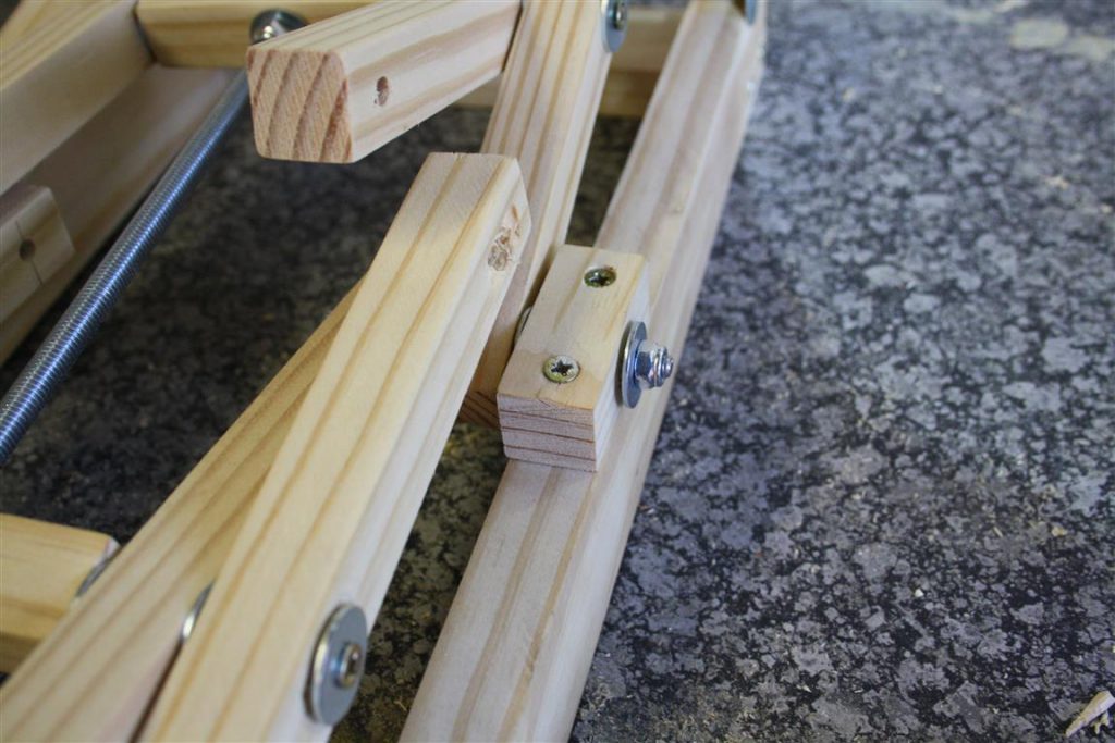
The important part of this step is the orientation of the scissor leg pegs when the sliders have been fixed. In the above image, it can be noted that the shorter sliders are attached to the outer pegs of the scissor leg while the longer sliders are attached to the inner pegs.
Also, the short sliders are positioned at the top at the front of the assembly while at the back, they are positioned at the bottom.
Step 5 – Bring it all together
 The last step of the DIY scissor lift assembly process will start by turning the adjustment rod (10mm rod “O“) to a point where it would allow the scissor legs to overlap and the holes in the adjacent pegs to line up.
Then place the adjustment mechanism on top of the base as indicated above.
The spacing between the large 6mm penny washers should be slightly larger than the width of the base allowing the sliders to move freely when the lift is being operated.
At this point, insert of the remaining 10mm dowels (6mm hole drilled in the center) through the cradle (“F“), that is attached to the base, and also through the 10mm hole in the outer bottom peg. Remember to once again add a 10mm washer between the adjacent wooden components that will be moving on top of each other.
The inner peg will only have a 6mm hole. Through it and also the newly added dowel, insert 1 of the remaining 6mm rods (“R“) and tighten using 6mm nuts and washers.
This step will be mimicked to attach the top of the lift also.
Complete!
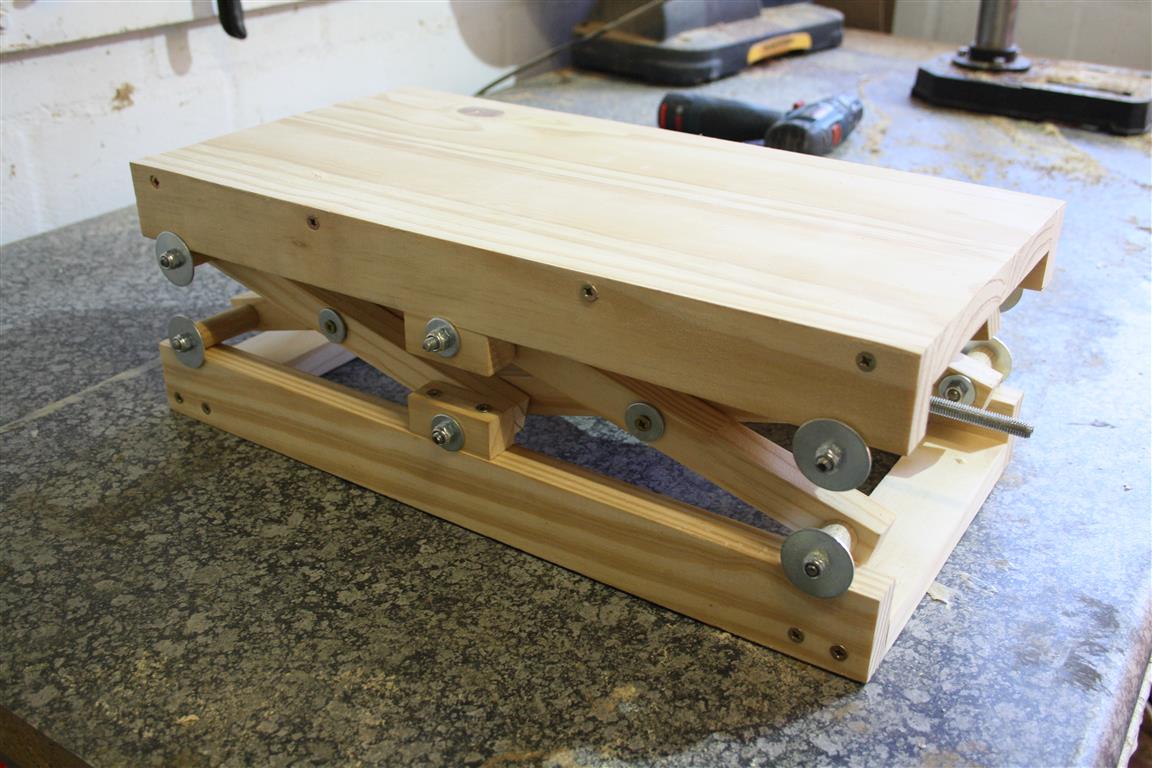
Once the lift is assembled it can easily be operated using a cordless drill (like the 12V Bosch I used) or with some minor alterations can be driven by an electric motor.
You can also opt to add a ruler to the lift as to observe the hight adjustment value.
Optional
You can also add a fixed motor to the lift to operate the platform motorized.
I appreciate your feedback. Any suggestions or questions can be added to the comment section below.
Thanks Jean! Great directions. The pictures make the page, so I have no problem following the instructions. A question, though. I am not sure if I missed it above, but how much weight can you put on the complete lift?
Hi Gregory
As this lift was only intended to level out stock when I’m using my bench drill, the load demands are not that aggressive. It is for this reason I did not perform an actual load test on the lift.
If I had to venture a guess I would say it would be able to comfortably lift and lower about 10 kg.
The material that it is made from can, however, be replaced with more robust material and it would be sure to handle more punishment.
Jean
What would you say is a good type of material to replace the current choice with? I have a need to level out some quite long pieces of white oak on a work bench that I’ll be gluing together into a mounted outdoor bar for my front patio. The pieces are 12 feet long and I’ve got 5 of them, so they are pretty darn heavy. I like fun projects like this and am kind of curious about putting it together.
Let me know what you think!
To be honest, I’d say it would have to be a trail and error type situation. I’d start by replacing the components that would carry the most load with a material like nylon. The sliders for example. Also maybe increase the OD of the threaded rod from 6 to 8mm.
The straight pieces like the scissor pegs wil be able to handle increased load if the wood is swapped out with aluminium square tubing.
this is an amazing invention easy to follow with the pictures.
Thanks for your hard work in putting this all together.
Hi Jean,
You are so good at carpentry.
Do you promote 12V Bosch ps130-2A or products made from wood?
Because I am more interested in your products made from wood.
Good tutorial.
Thank you.
Thank you Eli
The focus of this site is to help and inspire beginner and novice woodworkers by making procedures and plans available to them at no cost.
That being said, the ps130-2a is a great little drill and you won’t make a mistake to add it to your shop arsenal.
Jean
Hi Jean, wow great tutorial!!
I do a little tinkering at home and could use one of these, well maybe a slightly bigger one…. could I just double the measurements to make one twice the size or am I just being silly!?
P.s the little Bosch drill is ace!!
Hi Anthony
I’m very confident that the design can indeed be scaled. I would, however, use thicker cuts of lumber or even consider an more durable material when increasing size and load capacity.
Cheers
Jean
JEAN, THIS IS WHAT I WAS LOOKING FOR MY FRIEND, MY REGARDS
Great Hector.
If you have any questions please don’t hesitate to ask.
Jean
What changes would you recommend for making this lift with a motor instead of a drill. I’d like to modify this to make a lift mechanism for a train table for my son. I would use a on-off-on switch to control up and down motion and momentary switches to stop the motor at the max and min heights. Any help you could give would be greatly appreciated.
Hey Tonya
Modifying the lift to be motorized is something I have been thinking about, however, It might be more challenging than it appears to be.
In a scenario where the drill gets removed and a motor gets used to turn the rod (motor attached to the rod with a coupling or some other means), the motor would also need to be fixed at some point on the lift with what is generally called a torque arm. This is to allow the motor to turn the rod as opposed to the motor spinning itself on the rod (much like the tail rotor on a helicopter prevents the helicopter from spinning out of control).
This is all fairly obvious but where the tricky part comes in is where you would attach the torque arm on the lift itself.
Almost all of the points on the lift change in distance with respect to drive point on the shaft when the lift is being operated which means a fixed toque arm won’t work.
That being said, the simplest solution would be to change the drive point of the rod to the back of the lift where the rod is fixed. If you attach the motor to the rod at the back of the lift where the rod just turns inside the cross (component “E”) but the orientation of the rod with respect to the lift does not change while the lift is being operated, then the torque arm can simply be attached to the cross (“E”).
I hope this makes sense. If you have any other questions I would be more than happy to assist.
I will also look into modifying the lift myself and post content on that to https://youtube.com/woodshopjunkies as a few people have asked the same question.
Have a pleasant day.
Jean
Hi Tonya and Jean,
I would consider a slight re-design of the scissor jack. Instead of pulling the middle of the “X’s” together, pull the bottoms of the “X” legs together. For example take a look at the ATV/motorcycle lift found on Amazon at https://www.amazon.com/Motorcycle-Center-Scissor-Hoist-Stand/dp/B00E8HGCEY (I am not endorsing this product. This is simply a visual aid to show the design) . In this example the motor would have to be mounted to the top and therefore would raise and lower with the table. But if instead this entire jack was turned upside down, the motor would be mounted to next to the top (now the upside down bottom) and the “top” (now the upside down bottom) would raise and lower without affecting the motor.
Yes, you could consider buying and modifying that lift like I might have to for my application. But where would the fun be in that? My reason for considering the ATV lift is simply it’s ability to lift 1100 lbs.
Anyway, I hope this suggestion helps and if you are able to modify Jean’s design and get it working with a motor, I (and I’m sure everyone else) would love to see your working project.
Good luck
Dan
Jean – Great design, thank you. I am just about to put together my first real woodshop (small 12′ x 20′). I am considering about putting most of my “table top” tools on this type of device and place them along on wall inside of an encasement to rise and lower as needed. They would fit inside a basic empty box that is retrofitted with a flat top making it a useable workbench when that particular tool is no in use. Basically the tool would sit below the moveable workbench top until needed and then the top is removed, the tool raised for use. This design looks like it will serve my exact needs. I had considered using some sort of auto scissor jack as a lifting mechanism, but think that you design will serve the purpose equally as well without attempting to find the center point to mount the scissor jack. Once again thank you.
Interesting idea. With some planning and a bit of bulking up of this design, I’m sure it will be achievable.
Best of luck. Let me know how it goes.
Jean
Wow 🙂 Thank you posting this, I have been all over the internet trying find something that I could convert into a wheelchair lift. After an auto accident I can no longer lift my daughter’s wheelchair up the 10 stairs on the front of the house and now my 14 year old daughter will be in a wheelchair for several months following surgery. In addition to the lift we have to gut and rebuild a bathroom to make it accessible for both girls; this we have covered, but we are suffering sticker shock from the peds mobility’s price for the lift: $20,000 +/-!
This maybe the lifesaver I have been looking for! Keep making awesome things 🙂
jenny:)
Hi Jenny,
It’s terrible to hear about your daughter. I sincerely hope that you can adapt the design to make something that will make your life a bit easier.
Please be careful. 10 stairs it quite high so make sure to build a solid machine with robust materials. Consider hydraulics and be sure to install failsafe mechanisms.
Jean
You might be better off if riding a sled up and dowm. A small winch can pull several hundred pounds. They market them for attic and garage lifts and run connected to 110v Wall socket power. They are not more than a couple hundred dollars.
Hope this might help.
I was wondering what changes would need to be made for the scissors to move toward the opposite sides instead of to the middle? That way, one could reduce the chance of overloading the outer edge and cause toppling.
Hey Vernon,
Looking at this design, you would need to separate the two crosses. Also, instead of fixing the cross in the center of the lift you would need to move the fixing points to the outer points (where the sliders are fixed on this design).
The threaded rod would need to be changed to a two-directional threaded rod and instead of having it in the center, it would need to move to the top (or bottom) of the cross.
This will allow you to lift and lower both crosses by driving the same threaded rod. Because the crosses are fixed toward the outer edge of the lift the cross will move in that direction when the lift is raised.
Hope this makes sense.
Jean
Could you clarify why the rod would need to switch to be bi directional? Wouldn’t the movement of the connecting pieces E be the same?
The rod would need to push/pull the two E components closer/further from each other with nuts set into both. If you used a normal rod such a design would not work because by turning the rod you would simply be screwing it through the two nuts while the distance between the nuts would stay the same.
Keep in mind that this is not a design I actually developed and built. I am simply saying how I would go about achieving the above mentioned.
I need to have the device lift to 38″ above the floor. What dimensions would I use for ONE set of lifters, or could I use a SECOND level of lifters – and If yes what length?
Thank you
Hey Ed,
The lift I made has a max height of 12″. You require it to reach more than 3 times that. If you use this design then every component would need to be scaled accordingly as the height is proportional to the base.
Adding more lifters will give you more height but will also increase the height of the jack at its lowest position.
Depending on your load requirements, you might want to consider a different design.
Hope this is helpful.
Jean
Your component list for the threaded rod “O” Component does not specify the length. I’d appreciate your advice.
Regards Maurice
My sincerest apologies.
Component “O” is a 360-400mm(14.1-15.8inch) rod.
Hope this is helpful.
Jean
Hello Jean. Thanks for all the advice and information in your detailed instructions. I have made my version of the lift, it is 100 cm long at the base, the base is 43 cm wide and the legs are 50 cm long.
At present, I’m using my drill to rotate the rod to raise and lower the table.
I have one difficult problem – when the lift is raised to near maximum safe height which is 46 cm from the bottom of the base to the top of the table it is stable left to right but very unstable front to back.
For example, with only a weight of several kilograms located towards the front (on the centre of the table), the front “sags” so that the height is now only 44 cm, instead of 46 cm. Likewise, when the same weight is located towards the rear of the table the table height is 45.2 cm.
I’m happy to provide photos showing what is happening if that would be useful.
I’d appreciate your comments. TIA
Hey Maurice
Feel free to e-mail the pics to me at jean@woodworkjunkie.com and I’ll try my best to assist you.
Hi Maurice
I am planning to build the exact same size like you did. Do you mind sharing the measurements that you used please?
Or Jean, do you perhaps have measurements to convert to a bigger version like this? I want to use it as a standing desk converter for my laptop and screen
Kind regards
Lana
How is the motor is powered I seemed to miss that
Hey Chris
I used a drill to operate the lift. In the second video, I mount a drill motor to the lift to power it. It is explained in the video at the bottom of the post.
hi I am new just found you on you tub love your work. I am thinking of making your scissor lift for my miter saw in the all in one work bench
Hi Jean
I am considering using your lift (thank you very much) in my homemade table saw to raise and lower the inverted circular saw. Do you believe it would be rigid enough for that. Obviously I would be securing the lift to the table and the saw to the lift! 😉 Cheers Kevin
Hi Kevin,
I don’t think it would work in that way. Even the slightest movement on the blade can have dangerous results.
Thanks Jean
Hi Jean. I am attempting to make your lift and am very new to woodworking. My question is how to do this “lock nuts should be fastened to a point where the rod can still turn within the “E” component.”. Thank you for any help you can provide!
Laura
The lock nuts are not tightened onto the E component. This means that the gap between the two locknuts is slightly larger than the thickness of the E component. If the nuts are too tight then the rod won’t be able to rotate. I hope this makes sense.
Hey Jean,
Thank you for your design. Unfortunately I am in the US and I have to translate this into inches. The hard part is the sizes are crazy when they get converted to inches, so I am going to try and adjust the sizes to make it work. I will try and post my conversions and what I come up with. On another note, I did convert your build for the work bench to standard and I am very happy with the out come. I even managed to place my Dewalt table saw into the bench using the a floor jack to raise it. Let me know if you would like to see what I did.
Hi Ray,
That’s great news. You are welcome to send me a mail with your version of the design. jean@woodworkjunkie.com
Hey Ray,
I really would like to make one of these. I tried to convert to US but unsure if I converted correctly. How have you come along with your build? If you successfully built one using US standards? If sou could you please share with all? Thanks!
Hello I know you made this awhile back but I was curios if you knee how I could make this to keep the same lowest height setting but have a higher maximum height.
Hope to hear from you
For this design, you would need to increase the overall length (back to front) so that you can increase the length of the cross pieces. You might run into stability problems so beefing up all the components might also be necessary.
I want to make the scissor lift 30 inches. Can u tell me how long to make the arms . WhT size motor to lift 50 lbs .
Hi, this is a really cool design. I am building a sit stand desk and wondered if this design would allow me to raise the desk surface (30×60 inches). Could I put the two X’s perpendicular to the front spaced about 20 inches apart? Also rather than pulling from the center, could I pull from the top of the X s (motor would be mounted just under the surface of the desk).
Also, I need about 12 inches of lift from sitting to standing position. It looks like the size of this design was doubled, it would fit under the desk (30″ length) but only provide about 9 inches of lift.
I am going to make a motorcycle lifting workbench and these plans and instructions are the clearest I have found. I know I will have to scale the dimensions to suit, but based on your statement that the lift height is proportional to the base and your design has a lift height of 300 mm and base of 440 mm, I am going to use a scaling factor of 1:1.5 for the arms only because I don’t need to lift the worktop more than 500 mm.
The base of my lift will be 2400 mm, so this design with paired sets of arms will be perfect. I will have to choose stronger materials and probably use roller bearings on load bearing parts that move.
Wish me luch with my build!
Hi Jean. Thank you for allowing us your plans and showing us your process. For free! That is so rare. May you be blessed seven-hundred and seventy-seven fold for each heart you gladdened, like mine.
Love your photos, love your project. I want a more robust one for my telescope. When I want to see objects that are high in the sky, the eyepiece goes down to the ground almost. A lift would be nice so I don’t have to crouch or kneel to see through the eyepiece.
Awesome job.
I need to construct a scissor lift to raise and lower a wheelchair platform, 8′ X 4′, for a height of five feet with measurements in feet and inches. Can you help me with those plans?